Скачать с ютуб Thermal Analysis in Ansys Workbench | Heat Transfer - Conduction and Convection в хорошем качестве
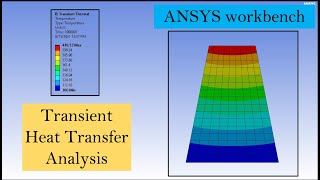
Thermal Analysis in Ansys Workbench | Heat Transfer - Conduction and Convection
1 год назад
Скачать бесплатно Thermal Analysis in Ansys Workbench | Heat Transfer - Conduction and Convection в качестве 4к (2к / 1080p)
У нас вы можете посмотреть бесплатно Thermal Analysis in Ansys Workbench | Heat Transfer - Conduction and Convection или скачать в максимальном доступном качестве, которое было загружено на ютуб. Для скачивания выберите вариант из формы ниже:
Загрузить музыку / рингтон Thermal Analysis in Ansys Workbench | Heat Transfer - Conduction and Convection в формате MP3:
Если кнопки скачивания не
загрузились
НАЖМИТЕ ЗДЕСЬ или обновите страницу
Если возникают проблемы со скачиванием, пожалуйста напишите в поддержку по адресу внизу
страницы.
Спасибо за использование сервиса savevideohd.ru
Thermal Analysis in Ansys Workbench | Heat Transfer - Conduction and Convection
Can you write me a review?: https://g.page/r/CdbyGHRh7cdGEBM/review / mech-tech-simulations / mech.tech.simulations / mechtechsimulations https://mechtechsimulations.com/ WhatsApp: +91 9488469801 Timestamps: 00:00 Intro 00:09 Workbench setup 00:30 Engineering data and material selection 01:01 Design cylinder geometry 03:18 Create mesh 04:01 Define boundary conditions 06:59 Analyzing results 09:05 Design fins 12:27 Update convection surface 13:38 Analyzing results with fins 13:54 Outro / mech_tech.90 / mechtechpage ANSYS Workbench is a powerful simulation software that can be used for a wide range of engineering analyses, including conduction and convective analysis. In this tutorial, we will walk through the steps required to perform a conduction and convective analysis in ANSYS Workbench. Step 1: Create a New Project Launch ANSYS Workbench and create a new project. Select the desired analysis type (e.g. thermal) and enter a name for the project. Step 2: Geometry Creation Create the geometry for your analysis using the Design Modeler tool in ANSYS Workbench. The geometry should include all relevant details, such as the size and shape of the object, as well as any boundaries or interfaces that will be relevant to the analysis. Step 3: Meshing Once the geometry is created, the next step is to generate a mesh. Meshing is the process of dividing the geometry into small, interconnected elements that will be used to perform the analysis. Select the appropriate meshing tool and specify the desired mesh size and other relevant parameters. Step 4: Define Materials In this step, we define the material properties for each part of the model. For example, if you are analyzing a metal component, you will need to specify the thermal conductivity, density, and specific heat of the metal. This information can typically be found in material data tables or online resources. Step 5: Boundary Conditions Boundary conditions are the constraints that are applied to the model. For example, you may want to specify a heat source or a temperature boundary condition on a specific surface of the object. These boundary conditions will be used to solve the conduction and convective equations in the next step. Step 6: Solve the Model In this step, ANSYS Workbench will use the input parameters from the previous steps to solve the conduction and convective equations. ANSYS Workbench uses the finite element method (FEM) to solve these equations, which involves breaking down the model into small elements and solving the equations for each element. Step 7: Post-Processing Once the analysis is complete, ANSYS Workbench will provide the results in graphical format. The results can be used to visualize the temperature distribution, heat flux, and other relevant parameters. You can also use the post-processing tools to generate additional plots, such as temperature vs. time, or to export the results in a format that can be used in other software. In summary, the steps required to perform a conduction and convective analysis in ANSYS Workbench include geometry creation, meshing, material definition, boundary conditions, model solving, and post-processing. By following these steps, you can obtain accurate and useful results for your thermal analysis.
Comments