Скачать с ютуб Distinguish the Fast and Slow Axes of a Quarter-Wave Plate | Thorlabs Insights в хорошем качестве
Distinguish the Fast and Slow Axes of a Quarter-Wave Plate | Thorlabs Insights
2 года назад
Скачать бесплатно Distinguish the Fast and Slow Axes of a Quarter-Wave Plate | Thorlabs Insights в качестве 4к (2к / 1080p)
У нас вы можете посмотреть бесплатно Distinguish the Fast and Slow Axes of a Quarter-Wave Plate | Thorlabs Insights или скачать в максимальном доступном качестве, которое было загружено на ютуб. Для скачивания выберите вариант из формы ниже:
Загрузить музыку / рингтон Distinguish the Fast and Slow Axes of a Quarter-Wave Plate | Thorlabs Insights в формате MP3:
Если кнопки скачивания не
загрузились
НАЖМИТЕ ЗДЕСЬ или обновите страницу
Если возникают проблемы со скачиванием, пожалуйста напишите в поддержку по адресу внизу
страницы.
Спасибо за использование сервиса savevideohd.ru
Distinguish the Fast and Slow Axes of a Quarter-Wave Plate | Thorlabs Insights
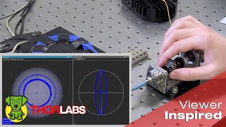
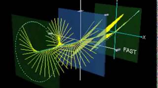
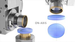
A wave plate has two axes, and light polarized parallel to the slow axis is delayed more than light polarized parallel to the orthogonal fast axis. The wave plate's retardance determines the delay difference. A couple of crossed polarizers can be used to locate an axis ( • Create Circularly Polarized Light Usi... ) but cannot identify the axis as fast or slow. However, by including a mirror in the setup and comparing optical power measurements with calculated values, it is possible to distinguish between the fast and slow axes of a quarter-wave plate. Note that this technique cannot be used to distinguish the fast and slow axes of a half-wave plate. The video includes an overview of the measurement setup and discussion of the conventions used to align and orient the optical components. The accurate interpretation of the results depends on these details, including whether the transmission axes of the generating and analyzing polarizers are parallel or orthogonal (crossed). Crossed polarizers are used in this demonstration, in contrast to a paper [1] that also describes the technique. The fast and slow axes of the quarter-wave plate are identified by comparing measurements of the power transmitted through the system to a pair of theoretical curves. The Fresnel reflection equations, as well as other equations, needed to compute these curves are provided. The refractive index of the reflective surface is required to generate these curves. Be aware that complex refractive indices can be written with a positive or a negative sign before the imaginary part, depending on the preferred convention. While either option is compatible with this approach, the chosen sign affects the interpretation of the curves. In this demonstration, the positive-sign convention was chosen. [1] Petre Cătălin Logofătu, "Simple method for determining the fast axis of a wave plate," Opt. Eng. 44, 3316-3318 (2002). 00:00 - Introduction 01:04 - Circular Polarization and Handedness Conventions 03:14 - Experimental Set Up 05:50 -Overview of the System and its Model Equations 07:01 - Power Measurements Acquired 07:31 - Fast Axis Distinguished from Slow Axis Components used in this demonstration include: - HeNe Laser: https://www.thorlabs.com/navigation.c... - Optical Isolator: https://www.thorlabs.com/newgrouppage... - Linear Polarizers: https://www.thorlabs.com/navigation.c... - PRM1 Rotation Mount: https://www.thorlabs.com/newgrouppage... - Wave Plates: https://www.thorlabs.com/navigation.c... - WPMQ05M-633 Quarter-Wave Plate: https://www.thorlabs.com/newgrouppage... - PF10-03-M03 Unprotected Gold Mirror: https://www.thorlabs.com/newgrouppage... - KM100 Mirror Mount: https://www.thorlabs.com/newgrouppage... - SM1D12D Iris: https://www.thorlabs.com/newgrouppage... - SM1L20 Lens Tube: https://www.thorlabs.com/newgrouppage... - SM1QA Quick-Release Lens Tube Adapter: https://www.thorlabs.com/newgrouppage... - S130C Power Sensor: https://www.thorlabs.com/newgrouppage... - PM400 Power Meter: https://www.thorlabs.com/newgrouppage... For more photonics how-to videos, visit https://www.thorlabs.com/newgrouppage...
Comments