Скачать с ютуб How To: Antique Radio Alignment в хорошем качестве
How To: Antique Radio Alignment
4 года назад
Скачать бесплатно How To: Antique Radio Alignment в качестве 4к (2к / 1080p)
У нас вы можете посмотреть бесплатно How To: Antique Radio Alignment или скачать в максимальном доступном качестве, которое было загружено на ютуб. Для скачивания выберите вариант из формы ниже:
Загрузить музыку / рингтон How To: Antique Radio Alignment в формате MP3:
Если кнопки скачивания не
загрузились
НАЖМИТЕ ЗДЕСЬ или обновите страницу
Если возникают проблемы со скачиванием, пожалуйста напишите в поддержку по адресу внизу
страницы.
Спасибо за использование сервиса savevideohd.ru
How To: Antique Radio Alignment
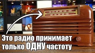
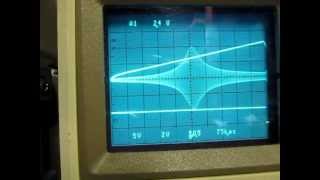
To get the best performance, a Superhet radio needs to be aligned. Based on the name, you might think alignment simply means to make sure the radio dial aligns to the correct frequency. That’s part of it, but there’s more. Our antique radio was originally aligned at the factory, so the original owners never had to think about it. Now that it’s aged and we’ve replaced so many parts though, a new alignment will be necessary to bring it back to peak performance. Essentially, an alignment is using radio frequency or “RF” generator to send a test intermediate frequency into the radio circuit. Then, using an instrument to monitor the results, the IF transformers and variable condenser are tuned for peak performance. As you’ll recall, a Superhet radio turns the carrier frequency signal into the critical intermediate frequency. The job of the IF transformers is to tune the intermediate frequency to be as strong and pure as possible. The main purpose of an alignment, is to adjust the IF transformers to do just that. If you’re a little fuzzy about the how’s and why’s of this, please see my earlier videos in this series where superheterodyning and IF transformers, are explained in detail. To do a proper alignment, it’s important to know the IF frequency the radio was designed for. This is sometimes printed on the chassis, but often, you’ll need to do a little research or find the schematic. In our radio, and in many All American Fives, the intermediate frequency is 456 kilocycles. 455 is also common, and rarely, some radios also use oddball frequencies such as 170, 210, 470 or others. I was fortunate enough to have not only located the schematic for our old Emerson 108, but also a useful sheet showing the parts list, general notes, and adjustment instructions. Aligning an All American Five radio is possible without the instructions, though, as the process is similar no matter the radio. As you can see, the instructions state that an external oscillator and output meter connected to the speaker voice coil terminals are required. The external oscillator is now more commonly referred to as an RF signal generator, such as the one I used shown here. I also own this fancier generator which in addition to AM, can be used to align FM radios and stereos. Instead of a multimeter, I used this oscilloscope. Either is fine, but I prefer an oscilloscope as it not only shows the output level but also waveform shape. I find that adjusting the output shape for maximum symmetry gives a slightly better alignment. Here, you can see the IF signal being injected into the radio from the RF generator on the left, and I’m monitoring the output on the oscilloscope on the right. It’s important to note that the RF generator adds a modulated audio tone to the signal, just as a radio station adds audio information to the carrier frequency. This allows us to measure the amplitude and quality of the tone at the speaker, while we adjust the trimmers for maximum performance. #radiorepair #radio #electronicsrepair Before I began, I made this quick drawing to show the recommended steps to align the radio and the locations of the trimmers that require adjustment. Step one is to turn the variable condenser to the unmeshed, minimum capacitance position. Step two is to connect the positive output of the RF generator to the grid cap of the 6A7 converter tube. I actually recommend clipping the output lead to the insulation of the grid cap wire instead of directly to the cap. There’s no high voltage on the grid cap, but still, this is safer overall, and as the instructions note, “always use as weak a test signal as possible when aligning the receiver.” The negative output from the signal generator can be connected to the radio chassis. For safety’s-sake, whenever you connect a test instrument such as an oscilloscope or signal generator, make sure the device under test is powered through an isolation transformer... and the test instrument is powered normally through your home wiring, not the isolation transformer. Having a device, especially one with a hot chassis such an All American Five radio connected to the same common as a test instruments is dangerous, and can ruin your equipment. #radiorepair #radio #electronicsrepair #restoration
Comments