Скачать с ютуб Raspberry Pi and Arduino communications using SPI with Python and CPP в хорошем качестве
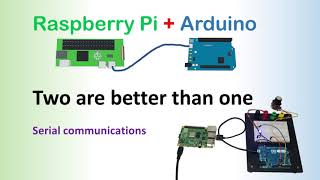
Raspberry Pi and Arduino communications using SPI with Python and CPP
3 года назад
Из-за периодической блокировки нашего сайта РКН сервисами, просим воспользоваться резервным адресом:
Загрузить через ClipSave.ruСкачать бесплатно Raspberry Pi and Arduino communications using SPI with Python and CPP в качестве 4к (2к / 1080p)
У нас вы можете посмотреть бесплатно Raspberry Pi and Arduino communications using SPI with Python and CPP или скачать в максимальном доступном качестве, которое было загружено на ютуб. Для скачивания выберите вариант из формы ниже:
Загрузить музыку / рингтон Raspberry Pi and Arduino communications using SPI with Python and CPP в формате MP3:
Если кнопки скачивания не
загрузились
НАЖМИТЕ ЗДЕСЬ или обновите страницу
Если возникают проблемы со скачиванием, пожалуйста напишите в поддержку по адресу внизу
страницы.
Спасибо за использование сервиса savevideohd.ru
Raspberry Pi and Arduino communications using SPI with Python and CPP
In an earlier I showed how you can control an Arduino from a Raspberry Pi using USB serial communications (UART). In this I show an alternative way to communicate between a Raspberry Pi and an Arduino by using the SPI (Serial Peripheral Interface) protocol. The advantage of SPI is that you can control multiple devices through one SPI bus. It can also be faster. It is however a little more complicated to understand and code and I've not properly used the full-duplex feature in my example code. For more details and to download the source code see: http://www.penguintutor.com/electroni... This video is created thanks to a suggestion from Gari Poter on the earlier video • Arduino and Raspberry Pi, working tog... The SPI ports on the Raspberry Pi are 3.3V only. They can be damaged by if a slave device raises a bus to 5V. If connecting to a 5V device then a level shifter should be used. Based on all models of the Raspberry Pi with 40pins, the pins for SPI0 are (physical pins): MOSI - pin 19 MISO - pin 21 SCLK - pin 23 CE0 - pin 24 CE1 - pin 26 Ground - pin 25 Different models of the Arduino have different capabilities and ports for SPI. The newer MKR series run at 3.3V, but the more common UNO runs at 5V. I tested this using a Freeduino UNO which has the advantage of being able to switch between 3.3V and 5V, but otherwise similar to the official Arduino. It did have the advantage of allowing me to test the connection was working using 3.3V prior to adding the level shifter. The ports on the Arduino UNO that are used are: MOSI - pin 11 MISO - pin 12 SCLK - pin 13 SS / CE - pin 10 (optional) Due to the voltage difference I suggest that you use a logic level convertor (sometimes called a level-shifter or voltage shifter) between the Raspberry Pi and Arduino. The model I used is the "4-channel I2C-safe Bi-directional Logic Level Converter - BSS138". This is designed for I2C, but also works well with SPI up to 2Mhz. For test purposes I have connected digital outputs 3 to 9 to LEDs and resistors to ground. I used a bar graph LED and resistor array for convenience, but did not use all the LEDs on the bar graph. I used digital pin 2 to test an input (moving between +5V and Gnd) and I also added a variable resistor so that I could measure an analog voltage on analog input A0. This is shown in the diagram below (for convenience this is turned 90 degrees compared with the earlier diagram). This allows the code to demonstrate two way communication, with the Raspberry Pi asking the Arduino to set digital outputs on or off and request the Arduino provide information about digital and analog inputs. The Arduino sends the relevant information back to the Raspberry Pi. This provides something that can be used as a standalone system, although it's really just a small demonstration of what you can do. Chapters: 00:00 Introduction to video 00:39 Introduction to SPI 02:37 The difference between UART / USB serial and SPI 05:48 Communicating with multiple devices by SPI 06:10 Handling voltage difference between Raspberry Pi and Arduino 07:24 Test setup 07:58 Creating my own protocol for sending data with bitmasks 09:32 Arduino code in C++ 10:58 Raspberry Pi code using Python 12:34 Summary and demo
Comments


![Serial Communication between Raspberry Pi and Arduino [1H Complete Tutorial]](https://i.ytimg.com/vi/jU_b8WBTUew/mqdefault.jpg)
![The Everything Interface: Desktop to Chip [USB to SPI, I2C, JTAG, UART, SWD...]](https://i.ytimg.com/vi/WIIR77fCHYc/mqdefault.jpg)