Скачать с ютуб Time Delay Relay circuit using 555 timer IC | Off delay timer Switch | UTSOURCE в хорошем качестве
Time Delay Relay circuit using 555 timer IC | Off delay timer Switch | UTSOURCE
2 года назад
Скачать бесплатно Time Delay Relay circuit using 555 timer IC | Off delay timer Switch | UTSOURCE в качестве 4к (2к / 1080p)
У нас вы можете посмотреть бесплатно Time Delay Relay circuit using 555 timer IC | Off delay timer Switch | UTSOURCE или скачать в максимальном доступном качестве, которое было загружено на ютуб. Для скачивания выберите вариант из формы ниже:
Загрузить музыку / рингтон Time Delay Relay circuit using 555 timer IC | Off delay timer Switch | UTSOURCE в формате MP3:
Если кнопки скачивания не
загрузились
НАЖМИТЕ ЗДЕСЬ или обновите страницу
Если возникают проблемы со скачиванием, пожалуйста напишите в поддержку по адресу внизу
страницы.
Спасибо за использование сервиса savevideohd.ru
Time Delay Relay circuit using 555 timer IC | Off delay timer Switch | UTSOURCE
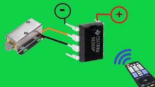
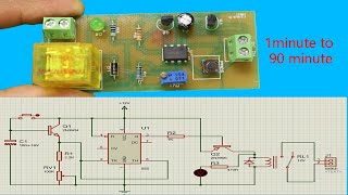
In this 555 timer project, I have shown how to make a time delay relay circuit using 555 timer IC to automatically turn Off the switch after a predefined delay. You can also adjust the off delay time up to 20 minutes. Download the PCB Layout for this 555 timer delay circuit from the following article https://easyelectronicsproject.com/mi... Visit the following website to get electronics components, modules at a very reasonable price https://utsource.net?source=YouTube IC chip: https://www.utsource.net IGBT: https://www.utsource.net/category/ele... electronic component: https://www.utsource.net Capacitor: https://www.utsource.net/ca/category/... diode: https://www.utsource.net/category/ele... find chips: https://www.utsource.net Transistors: https://www.utsource.net/sg/category/... Darlington: https://wwwutsource.net/category/elec... Sensors: https://www.utsource.net/home/sensors Required Components for the 555 timer project 1) 555 Timer IC 2) BC547 Transistor 3) 1000uF 16V Capacitor 4) 1k 0.25watt Resistors - 2 no 5) 10k 0.25watt Resistor 6) 1M Trimmer 7) LED 5mm - 1no 8) 1N4007 Diode 9) 12V SPDT Relay 10) Pushbutton 11) Connectors & IC Base 12) Acrylic sheet I have made the complete time delay switch circuit on a homemade PCB. I have used the 12V DC adaptor to supply the circuit. Please take proper safety precautions while working on 110V or 220V AC. You can also adjust the delay time of the light switch from the 10 mega-ohm trimmer or POT. If you want to use a 5V DC supply, then just use a 5V relay instead of the 12V relay. No other changes are required. After watching the video, you can easily design this Delay Timer switch circuit for your home. If you face any issues please let me know in the comment section. ------------------------------------------------------- WARNING: This video is for demonstration and educational purposes only. Each demonstration presents risks and hazards that must be fully understood before attempting. And should be performed only by professionals ------------------------------------------------------ #555timer ------------------------------------------------------ Thanks For Watching... ✅ SUBSCRIBE ✅LIKE ✅SHARE ✅ COMMENTS Website: https://easyelectronicsproject.com/ Facebook: / techstudycell Instagram: / techstudycell Telegram: https://t.me/techstudycell/ ------------------------------------------------------- Other useful videos: Mini Projects using 555 IC CD4017 • Mini Projects LED chaser circuit using 4017 and 555 timer IC • LED chaser circuit using 4017 and 555... IR Remote Control ON OFF Switch using 4017 IC & Relay • How to make wireless IR Remote Contro... LED strip dimmer circuit using 555 ic | PWM LED dimmer • LED strip dimmer circuit using 555 ic... How to calculate resistor value for LEDs in a circuit for 9V and 12V • How to select resistor value for LED ...
Comments