Скачать с ютуб Exploring the ECU hardware and testing - Part 3 (fault finding example with IGF signal simulation) в хорошем качестве
Exploring the ECU hardware and testing - Part 3 (fault finding example with IGF signal simulation)
3 года назад
Скачать бесплатно Exploring the ECU hardware and testing - Part 3 (fault finding example with IGF signal simulation) в качестве 4к (2к / 1080p)
У нас вы можете посмотреть бесплатно Exploring the ECU hardware and testing - Part 3 (fault finding example with IGF signal simulation) или скачать в максимальном доступном качестве, которое было загружено на ютуб. Для скачивания выберите вариант из формы ниже:
Загрузить музыку / рингтон Exploring the ECU hardware and testing - Part 3 (fault finding example with IGF signal simulation) в формате MP3:
Если кнопки скачивания не
загрузились
НАЖМИТЕ ЗДЕСЬ или обновите страницу
Если возникают проблемы со скачиванием, пожалуйста напишите в поддержку по адресу внизу
страницы.
Спасибо за использование сервиса savevideohd.ru
Exploring the ECU hardware and testing - Part 3 (fault finding example with IGF signal simulation)
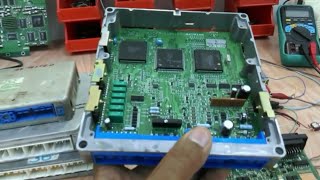
Exploring the ECU hardware and testing - Part 3 (fault finding example with IGF signal simulation) This video explains the ECU circuit board and demonstrates the way of crank and cam signal simulation to run the ECU and perform the different testing. The engine ECU controls the injection of the fuel to the engine and the timing of the spark to ignite it. It determines the position of the rotation using a Crankshaft Position Sensor so that the injectors and ignition system are activated at precisely the correct time. It uses also number of sensor to read the status of the engine in order to run the engine at optimum performance. The input to the ECU includes the following sensors: Crank Position Sensor Cam Position Sensor Knock Sensor Engine Coolant Temperature Sensor Manifold Absolute Pressure or MAP Sensor Mass Air Flow or MAF Sensor Oxygen/O2/Lambda Sensor Fuel Pressure Sensor Engine Speed Sensor Throttle Position Sensor The output from the ECU includes the following devices: Injectors Throttle body control Ignition coil Load relay output Malfunction lamp Fuel pump Idle control
Comments