Скачать с ютуб How Do Variable Condensers Work? в хорошем качестве
How Do Variable Condensers Work?
5 лет назад
Скачать бесплатно How Do Variable Condensers Work? в качестве 4к (2к / 1080p)
У нас вы можете посмотреть бесплатно How Do Variable Condensers Work? или скачать в максимальном доступном качестве, которое было загружено на ютуб. Для скачивания выберите вариант из формы ниже:
Загрузить музыку / рингтон How Do Variable Condensers Work? в формате MP3:
Если кнопки скачивания не
загрузились
НАЖМИТЕ ЗДЕСЬ или обновите страницу
Если возникают проблемы со скачиванием, пожалуйста напишите в поддержку по адресу внизу
страницы.
Спасибо за использование сервиса savevideohd.ru
How Do Variable Condensers Work?
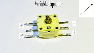
What is a variable capacitor? What does a variable capacitor do? Antique radio restoration. We’ve learned that the universe is full of electromagnetic waves, and our radio selects and amplifies a tiny fraction of those waves, in stages. The first stage is the antenna which, by nature of its shape and length, is tuned to receive a relatively narrow band of waves. The wave trap filters away frequencies we didn’t want interfering, and the antenna coil further narrows the spectrum into two different bands, while also adding a bit of signal boost. The next stage is the variable condenser, which allows us to choose specific frequencies from the two bands. So we can hear one station at a time. As we’ve learned, in the early days of electronics, capacitors were called condensers. A variable condenser is simply a capacitor, with variable capacitance. There are many variable condensers in our radio, but the only one officially called a variable condenser, is the one used for tuning. And it’s actually not one, but four variable condensers. The two larger ones are adjusted when the dial knob is turned. And the two smaller ones, are adjusted when the radio is aligned. We’ll discuss alignment in detail in a later section. On the schematic, the large variable capacitors used for general tuning are shown as capacitors with arrows going through them. The two smaller variable capacitors called trimmers, are shown with curved arrows as one of the conductors. There are five other trimmers in our radio. The one on the wave trap, and two each in the IF transformers. We’ll discuss IF transformers more in an upcoming section. The variable condenser looks different than the other capacitors in the radio, but it does have the same basic elements. The metal plates are conductors, and the air gaps are the insulator. Two sections of plates stay in a fixed position. These are called the stators. The other two sections of plates are attached to a rotating shaft. These are called the rotors. The radio’s tuning knob is connected to the shaft. As the shaft turns clockwise, the rotor plates gradually come closer, and closer to the stator plates. This is called meshing. When the rotor and stator plates are fully meshed, capacitance is greatest. When they are unmeshed, capacitance is lowest. And at points in-between, capacitance varies incrementally between high and low. To tune the radio to the lowest frequency on the dial, the shaft is turned fully clockwise, so the plates are fully meshed. To tune to higher-frequency stations, the shaft is gradually turned counter-clockwise, so the plates gradually unmesh. When the plates are fully unmeshed, the radio is tuned to the highest frequency. So, the lower the capacitance, the higher the frequency. And the higher the capacitance, the lower the frequency. And since the oscillator is also being tuned by the variable condenser, it’s frequency is adjusted in the same way. The tuning condenser can tune to specific frequencies, because its capacitors are arranged in circuit with the antenna and oscillator coils. And as we learned in previous sections, this arrangement creates a tuned circuit which will resonate at a certain frequency. Because the capacitors are variable, the resonant frequency can be changed. Variable condensers generally work fine in antique radios, but sometimes the metal plates will be bent causing a short. This is easily repaired by carefully straightening the plates. The variable condenser in our radio tested fine for shorts, but like everything in the radio it was filthy. After carefully marking the leads, I removed it from the chassis, gave it an ultrasonic bath, lubricated the shaft, and replaced the frayed wiring. Having the variable condenser by out of the chassis also gave me access to many capacitors that needed replacement. On the next segment we’ll talk about the next path our radio signal takes on it’s way to the speaker. The converter tube. To stay updated, please subscribe and click the bell. And if you like this video, give it a thumbs up. See you soon. #radiorepair #radio #electronicsrepair #restoration #capacitor
Comments